

Technical Note 10: Anatomy of a Tie-Down
Tie-Downs connect shear walls to foundations. The connections provide uplift resistance for wind and seismic forces. All tension components should be analyzed for strength, elongation, shrinkage and reliability. This technical note details a code based method for evaluating these properties. This method will work on any tie-down or holdown.
This page defines typical components. The balance of this technical note describes a step-by-step analysis of shrinkage compensated and traditional tie-downs.
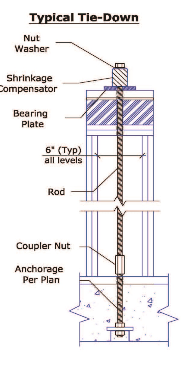
System Components typically include a threaded rod, bearing plate, shrinkage compensator, washer, nut, and coupler. In addition shrinkage/settling is considered a "component". For a given connection not all components are needed, but if used they must be analyzed. Shrinkage/settling should always be included.
Threaded rod is analyzed per AISC 360. Elongation should be calculated per AC391. A quick method is to use the elongation of a 10' rod length at the design load. This elongation is then adjusted using the ratio to actual length and loads.
Bearing Plates are sized and load rated per AC 391 and NDS 2005. The maximum allowable deflection at the allowable load is 0.040". Deflection is adjusted by the ratio of actual to allowable loads.
Shrinkage Compensators are rated by the manufacturer for the size of rod, load capacity and deflection. Deflection is adjusted by the ratio of actual to allowable loads. Deflection is the adjusted by the ratio of actual to allowable load.
Shrinkage Compensators also have a another property called delta r (ΔR). Delta r looseness is the average travel and seating increment. Delta r is not a function of load. This movement is part of and must be added in full to the system movement. (See AC316, 6.0.8)
Shrinkage/Settling is a system component. Shrinkage is elongation without load. If shrinkage is low (1/16"-1/8") a shrinkage compensator may not be needed. If shrinkage is greater than 1/8" we recommend a shrinkage compensator be used. Typically, engineers design for 1/4" to 1/2" of shrinkage per floor. Note: a properly applied shrinkage compensator should negate the need for a precise shrinkage calculation. (See Technical Note 15 for more information).
This page defines typical components. The balance of this technical note describes a step-by-step analysis of shrinkage compensated and traditional tie-downs.
System Components typically include a threaded rod, bearing plate, shrinkage compensator, washer, nut, and coupler. In addition shrinkage/settling is considered a "component". For a given connection not all components are needed, but if used they must be analyzed. Shrinkage/settling should always be included.
Threaded rod is analyzed per AISC 360. Elongation should be calculated per AC391. A quick method is to use the elongation of a 10' rod length at the design load. This elongation is then adjusted using the ratio to actual length and loads.
Bearing Plates are sized and load rated per AC 391 and NDS 2005. The maximum allowable deflection at the allowable load is 0.040". Deflection is adjusted by the ratio of actual to allowable loads.
Shrinkage Compensators are rated by the manufacturer for the size of rod, load capacity and deflection. Deflection is adjusted by the ratio of actual to allowable loads. Deflection is the adjusted by the ratio of actual to allowable load.
Shrinkage Compensators also have a another property called delta r (ΔR). Delta r looseness is the average travel and seating increment. Delta r is not a function of load. This movement is part of and must be added in full to the system movement. (See AC316, 6.0.8)
Shrinkage/Settling is a system component. Shrinkage is elongation without load. If shrinkage is low (1/16"-1/8") a shrinkage compensator may not be needed. If shrinkage is greater than 1/8" we recommend a shrinkage compensator be used. Typically, engineers design for 1/4" to 1/2" of shrinkage per floor. Note: a properly applied shrinkage compensator should negate the need for a precise shrinkage calculation. (See Technical Note 15 for more information).
System Strength evaluates all tension components. The system limit is the weakest element in the series.
System Elongation is the sum of the elongation of all components in series.
Elongation Limits vary by application, jurisdiction and wall height/length ratio. High wind elongation specifies a limit of .250”. (ICC ES AC 391, 3.4.2.1) Seismic elongation limits vary from 0.100” to 0.200”. Some jurisdictions specify both a rod and system limit (typically 0.125”/0.200”).
A New ICC ES Requirement
ICC ES requires shrinkage compensation devices to include the deflection at the allowable load (delta A) and average travel and seating increment (delta R). ICC ES Acceptance Criteria AC 316 (6.0.8) requires the following note be included in all reports:
The device average travel and seating increment, ΔR, and deflection at allowable load, ΔA, are additive and describe the total movement of the device at allowable load ΔT. For design loads, PD, less than the allowable load, PA, the total movement of the device, ΔT, is calculated as follows: ΔT = ΔR + ΔA ( PD/PA).
Bottom Line: “device travel and seating increment” (ΔR). Must be added in Full.
Significance
Because Delta r must be added in full, tie-down system analysis is more difficult. Delta r for shrinkage compensating devices varies from 0.000” up to 0.080”. System elongation consists of the sum of rod, bearing plate and shrinkage compensator deflections. If the system limit is 0.200”, staying within this limit may require enlarging the rod and/or bearing plates to limit the elongation. This would increase the cost of the tie-down. A lower Delta r, will often allow smaller rod and plates and may lower the tie-down system cost.
Designing a Tie-Down System.
To understand components and variables the following design examples are offered.
Tie-down goal. First, define the system requirements. See example at right. The examples solve the system requirements using different components.
Example #1 uses a 7/8" dia. A307 rod, an A36 bearing plate and a proprietary shrinkage compensator. For a given cost, standard strength rod (A307) usually provides the lowest elongation. Stiffness is a function of rod size (diameter and length) only.
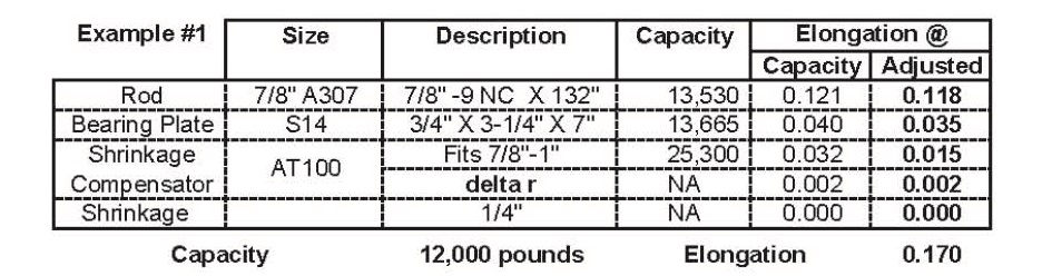
Table Notes: Rod baseline elongation is for a 10' length. The example doesn't check to see if the shrinkage compensator expansion is sufficient. Multi-story systems include a check for expansion adequacy.
A table insures that all item are included. The description, strength and elongation at allowable load are listed for each item. The lowest strength item is the system limit. In the example, rod strength limits the system to 13,530 lbs. The elongation for each item is calculated and summed. If the system elongation limit is exceeded, rod or bearing plates can be enlarged as needed. The following examples will help clarify alternatives.
Example #2 shows a 5/8" dia. B7 rod, a proprietary bearing plate, and shrinkage compensator. High strength rod usually provides systems with the lowest cost, but with higher elongation. This system meets the strength but not the stated elongation requirement.
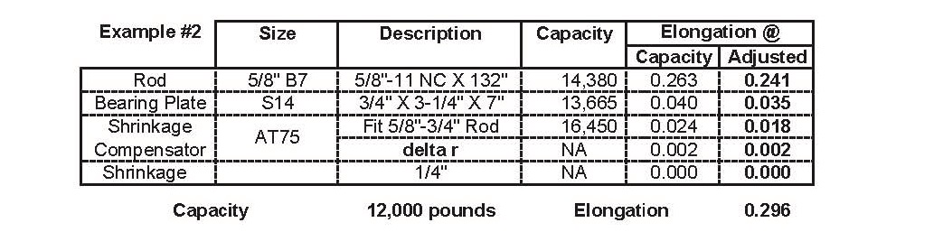
Note: The strength and elongation capacities come from "look-up" tables provided by the supplier. The tables take the manufacturers information and adjust it for a specific connection.
Example #3 shows a 3/4" Dia. B7 rod, with a proprietary bearing plate and shrinkage compensator. If the system uses a 0.200" elongation limit this combination also comes up short.
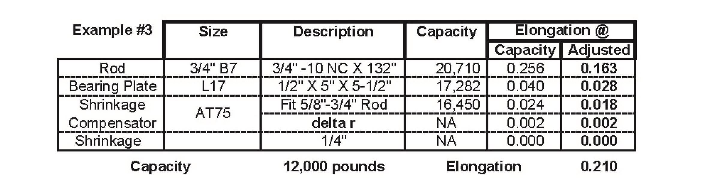
Component tables detail basic capacities for listed items. Allowable capacities are listed first. Adjusted capacities are calculated based on the specific requirements. In general the lowest cost systems use high strength rod. Systems with the lowest elongation tend to use standard strength rod (A307 or A36).
Example #4 is a single HD connecting a post to a foundation. (The bottom connection at the left.) The cross floor connection will be added in example #5.
Note: The holdown contributes 0.162" deflection. Shrinkage (at 1/8") is typical of a 3X pressure treated Hem -Fir mudsills. Shrinkage is added in full because there is no shrinkage compensator. This fails the 0.200" deflection limit.
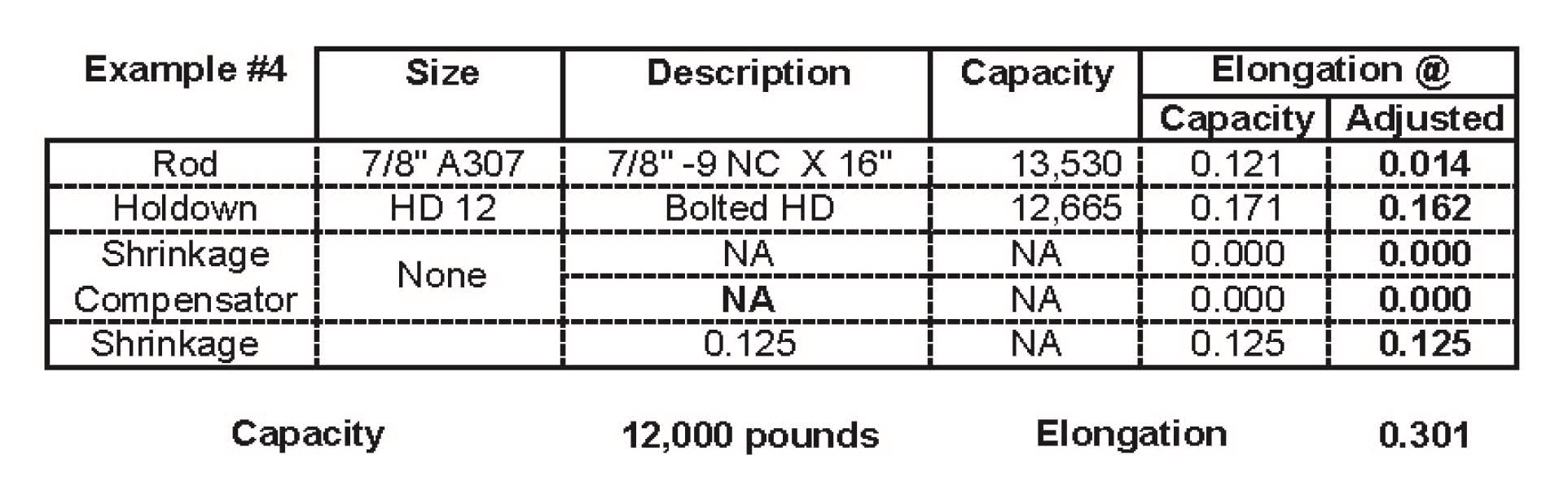
The HD 12 Holdown is from the Strong-Tie Catalog C-2011 Page 54. See Technical Note TN 15 for shrinkage information.
Traditional Holdowns-Multi Story
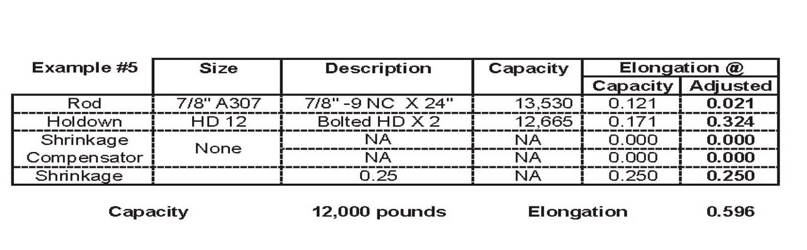
Example #5 shows a pair of traditional tie-downs spanning a floor and connecting stacked shear walls. The Floor system has minimal shrinkage because the floor joists are manufactured Wood I-Joists and the plates are specified at a 19% moisture content. Because two tie-downs span the floor the elongation for each tiedown must be added. This doubles the elongation.. This is the most overlooked item in wood frame construction.
Note: In June, 2010 ICC ES added the following Hold-down requirement:
"6.2.6.3. A statement alerting the report user to the fact that design of holddowns used in series shall account for the cumulative deformation of all holddown (tie-downs) within said series."
(ICC ES AC 155, June 2010)
When a complete analysis of a cross-floor connection is made it becomes obvious that the deflection introduced by shrinkage and two holdowns becomes excessive. A tie-down system that includes a shrinkage compensator is the clear performance choice over traditional tie-downs.
Traditional Holdowns-Multi Story
Example #6 shows a pair of traditional tie-downs spanning a floor and connecting stacked shear walls. The Floor system has "normal" shrinkage of 1/2" per floor due to solid sawn joists and plates delivered without seasoning.. Because two tie-downs span the floor elongation is doubled.
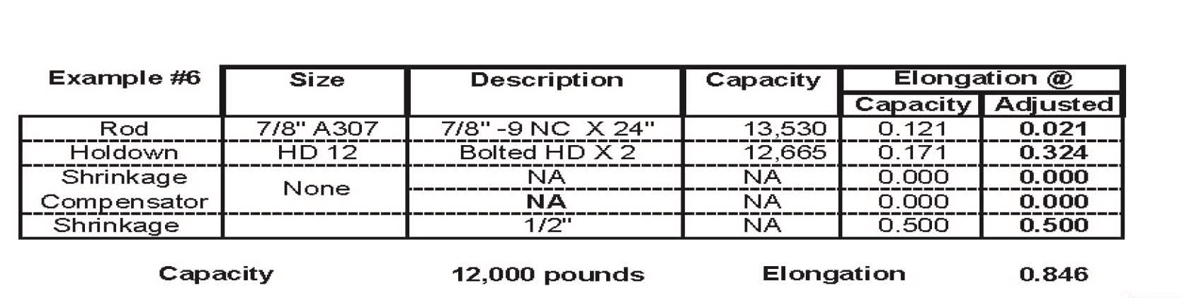
The shrinkage introduced by solid sawn wood will take several years to complete.
For the example I have provided expected shrinkage. Depending on your assumptions the shrinkage may be greater or less.
My opinion is Loose walls will not perform to code. A shrinkage compensator should be used across every newly constructed floor system and standard tie-downs should only be used on solid concrete decks.
For more information on this subject please see Technical Note TN 15 Shear Walls, Shrinkage and Lateral Drift.
In their catalog my competitor states: "For holdowns, per ASTM test standards, anchor bolt nut should be finger tight plus 1/3 to 1/2 turn with a hand wrench with consideration given to possible future wood shrinkage…."
I suggest you do your own analysis and consider a shrinkage compensated tie-down system.